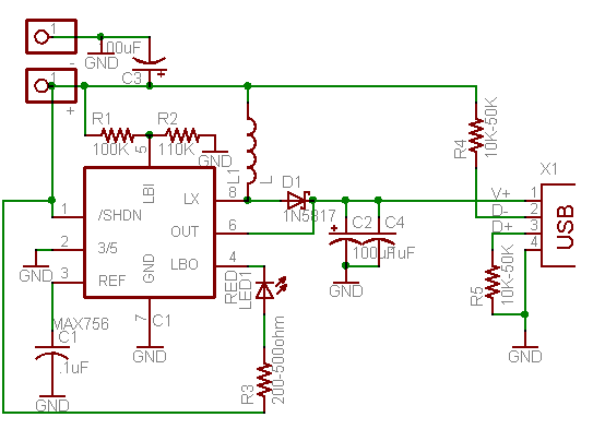
for more detail visit infoanda/hobby
If you a bit confuse about how to pin out the USB connector, where is pin 1 and not 4, here is the picture :

4 pin USB A / USB B / mini-USB jack connector at the controller, aka your Computer USB port.

4 pin USB A or USB B plug connector at the peripherals, USB Device, aka your Mouse, your keyboard, your USB Flash Memory.
USB pin assignment as follows :
Pin 1 -- VCC (5 VDC)
Pin 2 -- D- (Data -) typical cable color is White
Pin 3 -- D+ (Data +) typical cable color is Green
Pin 4 -- GND (Ground)
and if you guys want to order PCB online, try this site, www.pcb123.com

1 comment:
Well written article.
Post a Comment